Engineering
PLM engineering
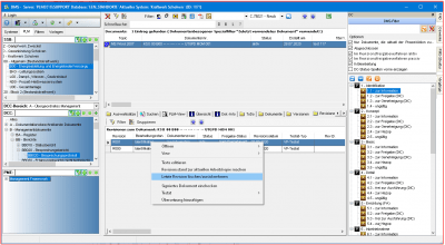
The process-oriented central SQL database allows the technical relationships and fundamentals to be generated and managed in an object-oriented manner. All engineering processes are mapped from the requirement specification to the specification sheet and carry all necessary information in a data and document pool, from the conceptual design to basic and detail engineering to the as-built documentation.
An integrated knowledge management is the most important central component to achieve transparency and innovation in the company. Every knowledge documentation is immediately displayed completely and correctly when a business process is completed.
That means for planning:
- PCycle times are shortened
- PThe goal is the completion of a complete service process in one step
- PThe quality management is integrated and continuous
- PPlanning processes are simplified despite their complexity because existing knowledge can be integrated into new projects
- PEffectiveness through standardisation, the reduction of the variety of methods automatically increases the quality of the results and reduces throughput times
- PIncreasing decision-making competence through transparent knowledge
- PIncrease in automation through rule-based processes
- PSubsequent documentation is usually subject to additional costs and time
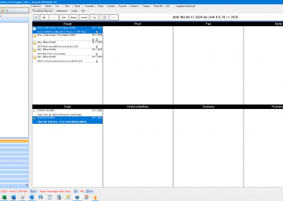
- PDocument management qualified for the process industry considerably reduces the time needed to search for and access information and documents. The mere fact that decisions can be made on the basis of immediately available knowledge means that such investments pay for themselves in a very short time. The greatest benefit is the integrative complete recording of business processes available in PLM-PLANET.
- PWith a "passive" archive this main benefit is not accessible in the long term


PID - Process technology
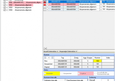
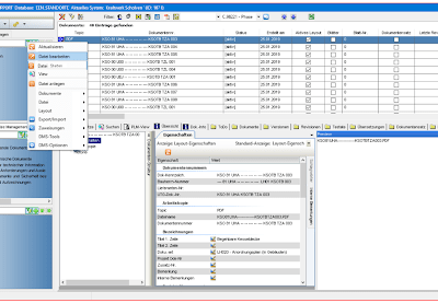
PLM-PID can be used to create, modify and manage process and P&I flow diagrams. Use the full potential of your know-how by fully integrating your engineering database. Fully automatic identification systems and online control to avoid double numbering are just some of the many highlights of this planning module.
- PPipe class compliant fitting selection
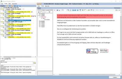
- PBidirectional working with DMS and PDE
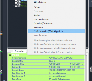
- PDatabase link to the 3D model
- PFlow charts as standard DWG/ DWF
- PCreate your process engineering flow diagrams according to your plant numbering in accordance with ANSI, KKS, RDS-PP and factory standards. PLM P&ID can work with any desired system
- PFull integration of the process engineering database, PLM P&ID synchronises the drawing with your process engineering bidirectionally
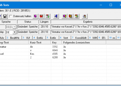
- PLabels are automatically updated. Line flags automatically adapt to the direction of flow
- PSmart drawing transitions
- PYour know-how from other projects, copy in the block-line process not only the graphic, but also the associated process engineering including all process engineering information
- PIntelligent job lists to automatically transfer changes from process engineering or other drawings into the current drawing
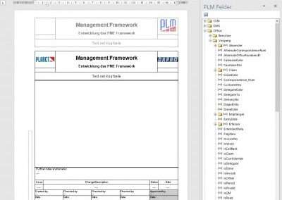
- PIntelligent drawing head, the drawing head is automatically filled with revision entries and corrected
- PIntelligent symbol library, automatic settings for actuators, labels and connectors
- PLabels are automatically aligned
- PIntelligent media are always displayed correctly
- PIntelligent linking of AutoCAD objects with the process engineering database

Latest Product News:
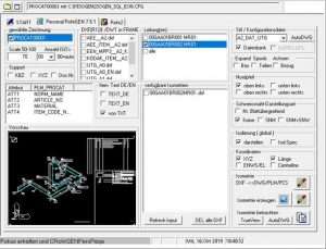
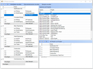
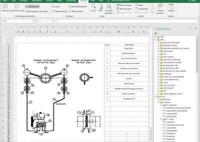
PID - PIA automatic process engineering
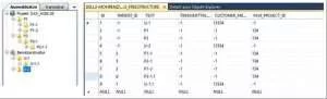
PLM PIA generates a PID fully automatically. A component configuration and an Excel transfer are the basis.
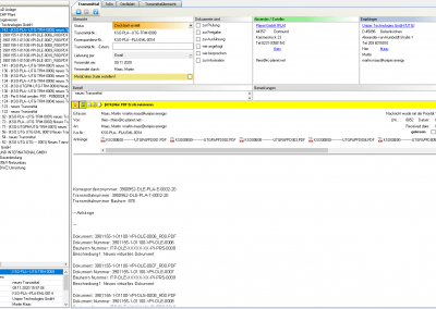
The project manages the individual Excel files, which are the basis for the design of the automatic P&ID construction. In the transfer file the parameters and the individual modules are provided. The actual assemblies and the project drawing creation remain in PLM Planet and are controlled by the new automation.
The assemblies, their attributes and their multilingualism are managed and organised in a management program. Since each assembly can have different attributes, each assembly is linked to the variable attribute definition. In the order, the specific attributes are then filled with the content in the selected project language.
Before the transfer to PLM-Planet, the attributes are filled with the transfer data using the xls transfer file created by the design program. Missing information is queried in a dialog.
The variable attribute link in PLM-Planet makes the corresponding entries in the drawing. The attribute names in the database match the attribute names in the individual blocks of the drawing. If an assembly is used in a project and several languages (up to three languages at the same time) are agreed upon, the corresponding attributes are prompted to enter the values. If these parameters are transferred from Excel, the values are taken from the transfer file.


Latest Product News:
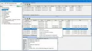
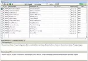
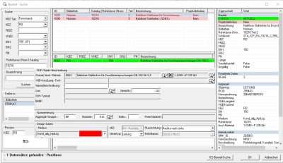
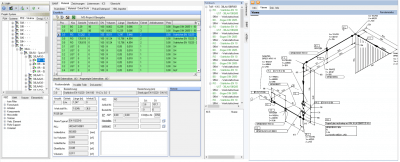
PDE process data engineering
PLM-PDE and process engineering are the heart of plant engineering. This is where the basic technology of the plant is determined, components are dimensioned and, together with the process flow diagrams, the basis for 3D planning and I&C technology is laid.
This includes lists, reporting, plant and equipment documentation, photo navigation, automatic labelling, navigation from the plant structure, typical creation, VT object-related photo documentation, room interfaces of the VT objects, flow charts as standard DWG/DWF.
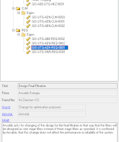
- PForm the unique process engineering structure of your plant in accordance with your identification system as per EN 81346, KKS, RDS-PP or a factory standard
- PNavigate using extensive filter and search options
- PForming, processing and managing assemblies of nozzles, connections and equipment of process engineering objects
- PDetailed information about the complete life cycle of process engineering with references to the documents
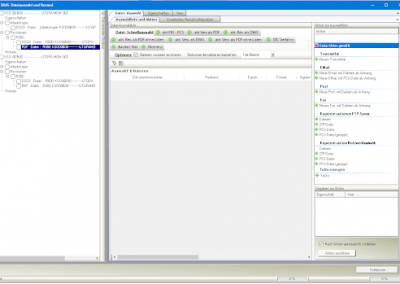
- PPLM list management as a universal tool for making detailed information visible and/or editable at specific points in PLM
- PView and/or edit the individual columns of your lists via the rights and roles system
- PAutomatically create data sheets and commissioning reports
- PThe list system to filter, group, prepare and calculate data, Multi Edit to perform mass processing
- PCatalogues with typicals including automatic updating of documentation
- PData output from the VT database into Excel for external editing and re-importing
- PCustomers use Excel lists as templates and fill them with PDE or output them as reports
- PAutomated translations of PDE lists, also according to customer specifications
- PRevise, version and save PDE lists in DMS, comparison of different revision levels, differences and new features are automatically highlighted
- PThe advantages of a fully integrated engineering database
- PPDE knowledge base is always and everywhere know-how to be used for other PDE projects


EMSR electrical, measurement and control technology
EI&C electrical, measurement and control data such as actuators and sensors are taken from the latest P&ID database control technology
taken over.
Data consistency to PDE, PID and LET (E-/MSR technology)
Organisation of step chains and sequence programmes
Navigation between P&ID, 3D and FBD (function chart)
Derivation of signal lists - Interlocks - Alarm specifications - Tables of contents
Comprehensive plausibility check
FBD function plan
- PPreparation of function plans according to EN and VGB R 170 C
- POrganisation of step chains
- PData consistency with P&ID, 3D and PDE
- PSignal lists, interlocks, alarm specifications, tables of contents
- PThe function chart can be output as a PDF document
Loop and HookUp
Actuators and sensors are assigned to the stored Typical and HookUp.
Because behind the HookUp of the measuring points there is a set-up plan, quantity structures and prices
a calculation is possible.
Signals and actors
Signals and actuators are assigned to the Typicals and HookUps in a qualified manner.
Switchgears
The connection of the power and control connection from the actuator to the module in
Control cabinet is specified. Electrical circuit diagrams are assigned to the modules as typical.


Latest Product News:
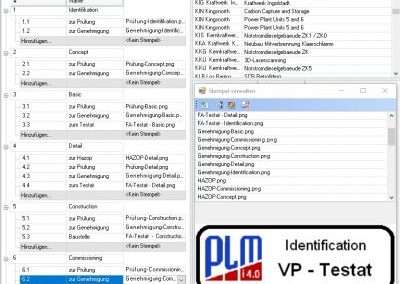
CEM CE, SIL, HAZOP Risk Management
CEM conformity procedures
- PCE label
- PMRL Machine Directive
- PPED Pressure Equipment Directive
- PDBRL pressure vessel directive
- PATEX Hazardous Atmospheres
- PHAZOP Hazard and Operability
- PPAAG forecast - finding - assessing - countermeasures
- PSIL Safety Integrity Level Functional safety
CEM application into one unit:
The task of the application is to generate data and documents for a unit and make them available for hazard analysis and risk assessment.
CE certification is being prepared. The unit has its own technical data, which are assigned according to the type.


Latest Product News:
P3D - 3D Layout Planning
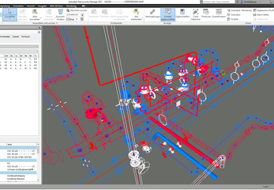
PLM-3D opens up a new world in 3D piping and equipment modelling for the planner by using a 3D-XML technology to capture hierarchically structured data. The XML-supported basic technology of PLM-PLANET decomposes each pipe, component and part into its graphic basic bodies, which are assembled via a 3D-XML construction manual and can be exchanged platform-independently.
Other highlights include playful modelling in the 3D system with data consistency to the P&ID, line routing, integrated steel construction profiles, stairs, etc. Collision control, automated parts lists, production and weld seam isometrics, import and export to Rohr2, component libraries according to DIN, EN, ANSI, plausibility control via PCL. In P3D the VT-Tree is also the central instrument, as it is also a graphical view of the database, all information and changes are immediately available. The equipment is generated via the tree and nozzles / connections are assigned as specified in the process engineering.
The pipes are the basis for the allocation to pipe classes and thus to the material system.
The 3D model of a plant today serves as the linchpin for the coordination for the construction of a plant.
Quantity frameworks for parts lists are determined, layout plans, fire protection plans or isometrics for the production of individual pipelines are derived. The 3D model of a plant also serves as a collision check and can be used as a basis for maintenance. PLM P3D is the tool of choice here.
PLM P3D offers the following features:
- PUse the possibilities of component and variant design to obtain an intelligent 3D model, change technical parameters and your 3D model will automatically adapt.
- PUse the intelligent tools for steel construction such as platforms, stairs and railings.
- PUse the integration of your process engineering database


P3D - PMx 3D Equipment Design
PMx is a 3D-XML variant technology for modelling equipment. The XML-supported basic technology of PLM-PLANET decomposes each line, component and part into its graphic basic bodies, which are assembled via a 3D-XML construction manual and can be exchanged platform-independently, i.e.
playful modelling in the 3D system including equipment, line routing, integrated steel construction profiles, stairs etc. The equipment is generated via the tree and connections are assigned to nozzles.
PLM P3D offers the following features:
- PUse the possibilities of component and variant design to obtain an intelligent 3D model, change technical parameters and your 3D model will automatically adapt.
- PUse the intelligent tools for steel construction such as platforms, stairs and railings.


Latest Product News:
P3D - 3D Isometry and Material Management
Isometrics are automatically derived from the P3D model.
- PGeneration of manufacturing isometrics
- PWeld seam placement and labelling
- PData consistency between P3D and PID
- PAutomatic dimensioning
- PIndividual and total parts lists
- PAutomated position labelling and sheet layout
- PPreparation of welding seam documentation
The MAT module generates a detailed parts list with material, weight and tender text from the 3D model. Specifications and certificates can be stored for the individual components.
A welding seam plan is generated automatically.
Calculations of weight, volume, painting surface and insulating material with insulating cladding are carried out. The materials are shown project-oriented in a PROCAT and can be added up across plants. PLM creates a material BANF, which can be processed in enquiries, offers, stock and assembly.


NAV Planning Supporting 3D Navigation in Navisworks
NAV is a module for planning supporting 3D navigation with data and documents from the PLM system.
The trade structure with integration of DMS controls the creation and modification of a 3D model.
Thanks to PLM-NAV it is no longer necessary to search through drawing or revision lists to reference the desired objects.
When navigating through the plant, click on a component and you immediately have all planning and data information available. By linking NavisWorks and the PLM-PLANET database via PLM-NAV, it is now possible to call up the information of every component recorded in the database in a 3D model.
Now select a specific area in your project and mark the objects required for your planning.
With a click of the mouse, PLM-NAV will then put together the corresponding drawing (regardless of the number of sources). In the NAV, the P&ID TAG object is directly connected to the 3D component, so that the correct circuit can be checked directly. PLM NAV starts the 3D construction with P3D directly from the NavisWorks model and updates the model after the changes have been made.
External 3D parts are linked to the database to gain access to the PLM database.
